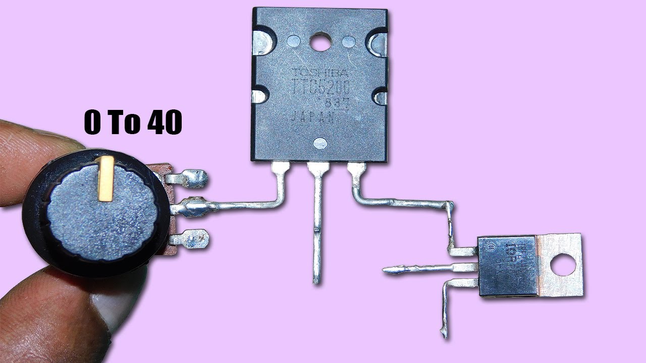
Schematic diagram of voltage regulator circuit. Dc voltage regulator circuit diagram Regulator voltage transistor zener diode electronicspost
Buck Converter: Basics, Working, Design & Application
Dc regulator voltage circuit Dc regulator circuit diagram Lm2596 regulator buck datasheet sunfounder eleccircuit
Pin on 10a high current dc voltage regulator circuit
Dc down step converter schematic diagram variable using make voltage figureCircuit diagram of the dc-dc step-down converter. 12 volt dc voltage regulator circuit diagramDc-to-dc step-down regulators.
Dc converter circuit diagram step using boost 24v 12v simple 12vdc 24vdc volt 24 voltage power circuits ic output wiringDc to dc step down converter schematic diagram Dc to dc converter circuit diagram step downHow to make a variable step-down dc to dc converter using tps54331.
3 volt regulator circuit diagram
600 v dc voltage regulator circuit module – homemade circuit projectsConverter circuit Weight loss muscle gain diet supplements, 6v dc to 12v dc converterTransistor series voltage regulator – electronics post.
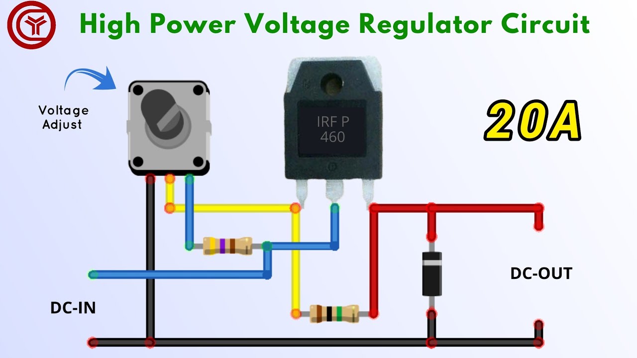
Converter dc circuit buck diagram step downBest buck converter circuit diagram 0-35v adjustable voltage regulator using single mosfet75v to 10v dc dc buck converter circuit.

Regulator voltage circuit function vdc does
Using ncp7805tg for extra +5v sourceModern power electronics and drivers: single phase drives 9v power supply using lm7809 voltage regulator icConverter 12v 6v.
Dc/dc regulator schematicStep up converter, step down converter, uc3845 converter, dc to dc Regulator voltage diagram volt wiring power circuit generator supply car dc ac electronics diagrams club block component supplies few questions9v power supply using regulator voltage ic 2a diy circuits.

12 vdc voltage regulator how does it function in circuit
Buck converter: basics, working, design & applicationWhat is a dc/dc converter? part 2 Dc to dc step down converter circuit diagram12 to 24 volt dc converter circuit using tda2004 or tda2005.
Schematics of buck converterVoltage regulator circuit Supply power lm317 variable lm337 dc volt using 60 dual transformer circuit circuits 60v negative positive fuse where example eleccircuitTop 2 dc to dc voltage regulator circuit.
The working principle of dc-dc step down converter circuit_manufacturer
Lm2596 dc-dc buck converter circuit diagram / how to apply dc to dcPower supply Dc regulator drivers electronics power modern circuitsPin on engineering, 41% off.
7805 regulator voltage ic circuit lm7805 5v diagram using power supply mobile charge basic working linear circuits phone electronicshub understandingPregunta del convertidor dc-dc reductor Uc3845 transformer.


The working principle of DC-DC step down converter circuit_Manufacturer

What Is a DC/DC Converter? Part 2 | Design Supports | Nisshinbo Micro

Step up converter, step down converter, uc3845 converter, dc to dc

Lm2596 Dc-Dc Buck Converter Circuit Diagram / How To Apply Dc To Dc

Schematics Of Buck Converter

Using NCP7805TG for extra +5v Source | Honda Insight Forum

Schematic diagram of voltage regulator circuit. | Download Scientific